Project Credit: Bernzomatic Torchbearer John Melton
Directions
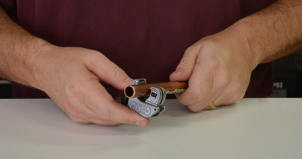
STEP 1: CUTTING COPPER TUBING
I like to slice my copper pipe up with a mini tubing cutter. This tubing is super easy stuff to work with. You simply put the round blade on your cutting mark and spin the cutter around the pipe. Every few times around, you just give the little wheel that closes the jaws tighter a little twist. In a less than a minute, the cut is done. Snap.
STEP 2: DRY FIT PARTS
I take a quick swipe at the fresh cut edges with a piece of sand paper to knock down any slight flaring or bur on the edges. I've learned that sometimes jamming freshly cut pieces together for a test fit can cause a situation where you can't pull them back apart. I've ruined some that way, so it's worth a few seconds of sanding.
I like to test build most of my project before soldering it together. I can work out any problems that pop up and tune the fit, before it gets too permanent.

STEP 3: MEASURE THE FITTING'S DEPTHS
The design needs some exact sizing.Knowing just how much tubing will disappear into the joining fittings is essential. I slip a straight piece into the fitting, mark it with a pencil, and pull it out to measure the lost bit. It lets me know how much to add to to my pieces between all the elbows, couplings, and the various doodads that will be added to the assembly.

STEP 4: MAKE A TEMPLATE
Because I was wrapping copper tubing around and into a box, I made a simple template the size of the back. I marked it into quarters to help orient where I wanted to locate some of the transitions and features.
Check out the bronze colored nut above the valve on the upper left of the photo below. I knew it would be difficult to fit those two threaded penetrations into the box so close together, so I added a "union." The union is a special, threaded piece which allows me to attach my, soon-to-be pre-fabricated pieces together and take them back apart.

STEP 5: FINAL CUTS (MOSTLY)
With a template in place, most of the final pieces could be sized, cut, and pre-assembled for the main section of plumbing.

I left a few of connective lengths a little long. I'd trim them down when I had more precise measurements. If I mis-measured the holes I'd be drilling in the box and the whole thing was permanently soldered together, I'd have a big problem. Better to trim the tubing later friends.

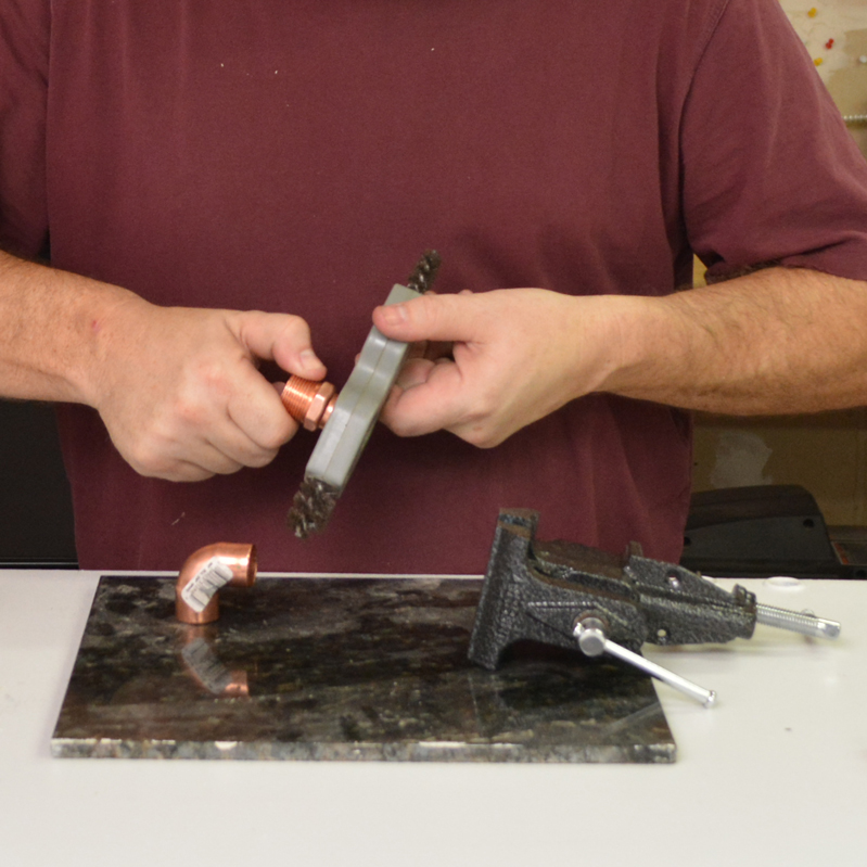
STEP 6: CLEAN THE PIECES
Both mating surfaces should be cleaned with sandpaper, emery cloth, or a special wire brush designed for the task. Clean, un-oxidized copper is much happier copper to accept solder and let it stick.

STEP 7: FLUX
I apply a thin layer of flux to the touching surfaces of the mating pieces with a cheap, acid brush. You can find them by the welding stuff at the hardware store. (The flux looks a bit like butterscotch dessert topping, but I don't think it tastes like it.)

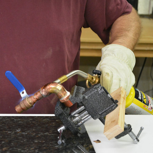
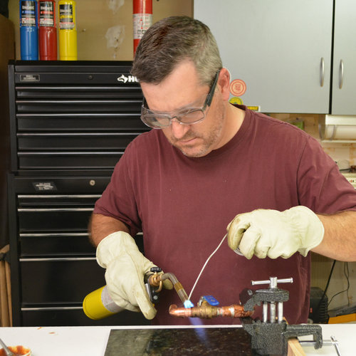
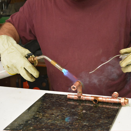
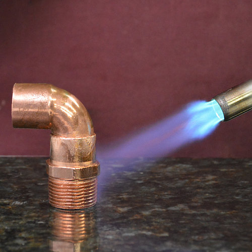
STEP 8: FLAME ON!
My blowtorch of choice is the Bernzomatic TS8000-MAX HEAT TORCH. It's my buddy. The TS-8000 is one of Bernzomatic's premier torches, by fueled by either propane, or my choice of the day, hotter-burning MAP-Pro.
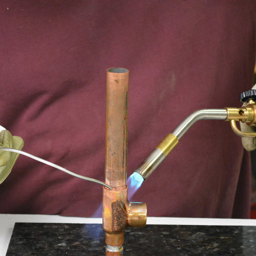
With a piece of my assembly clamped firmly (but not tight enough to bend the copper) I laid some serious heat on the fitting. Heating the fitting, rather than the tubing or the joint helps draw the solder into the joint at the proper time.

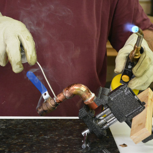
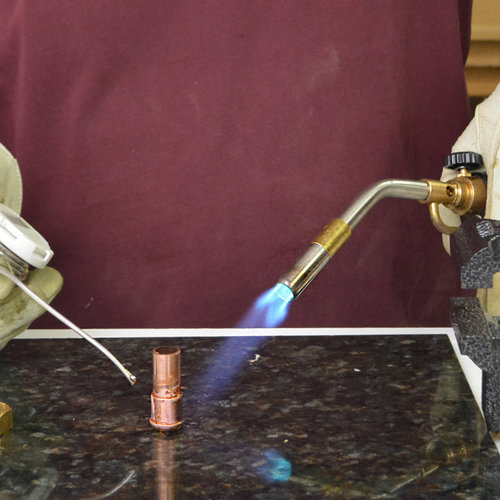
It only takes about 30 seconds or so to reach the proper heat with this torch. Once the flux starts to bubble and sizzle like butter in a salute' pan, I start gently tapping an extended piece of solder right above the joint between the pieces. It's either ready to melt or it's not, no in between.
Once it's hot enough,...slurp! The molten, silver metal gets sucked into the gap and flows quickly around the piece.
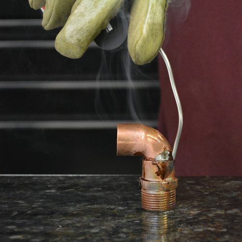
There are plumbers that are absolute pros at leaving a beautifully finished joint with this technique. Their expertly soldered connections look jewelry perfect. Mine do not look quite that neat. In fact, for these steampunk creations, I like a more rustic, almost post-apocalyptic look. I intentionally slap a little extra solder on there to run and drip a little.

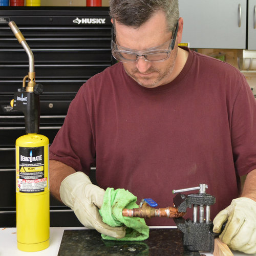
With all the pieces in the current group soldered, a damp rag quickly quenches the heat.
Be careful, wet gloves conduct heat a lot more than dry gloves. Don't boil yourself grabbing the piece too early after handling a wet rag.
A wipedown is the only cleaning I do on my Steampunk stuff. I like the discoloration, patina, and scorch marks left on the copper for character. In fact, I don't even peel price tags and UPC stickers off, I burn them in to a crisp, leaving more of that delightfully cooked appearance.

From there it's a game of rinse and repeat: clean, flux, flame, solder, and cool. I fabricate multiple mini-assemblies of 3-4 components before adding them onto the ever growing, spaghetti of my main creation.
The copper section was about 90% complete when I moved to the next step, the box base. In fact, it was more than just a box base...
THE STEAMER TRUNK
Poking holes in a perfectly good box

I found this super-cool mini-trunk at a craft store. Originally, I was going to build something similar, but buying a finished piece also saved me a ton of time on the project.
The craft store had all kinds of cool boxes and knick-knacks I could imagine making into a Steampunk lamp. How about one of those hollow, leatherbound books? A bird house? I'm sure the purveyors of fine knickknackery at import decorating shops also have piles neat stuff crying to get modified into a steampunk lamp too. Answer that cry!
STEP 9: MARK THE HOLES
Measure, measure, measure. It's not cool to poke holes in your newfound, classy mini-trunk and find out your freshly soldered plumbing misses the mark. Sharpen your pencil and take your time.

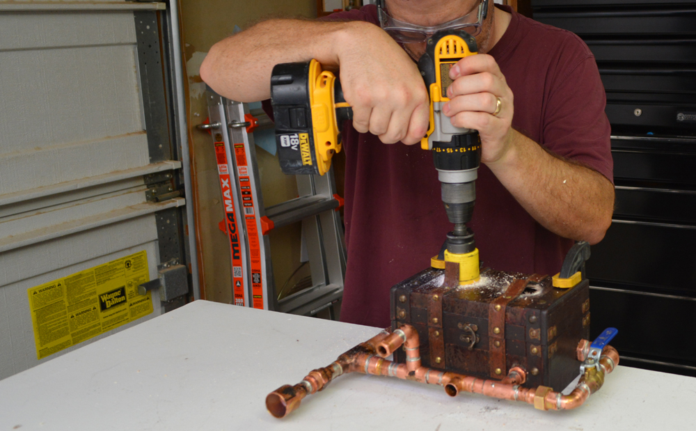
STEP 10: DRILL, BABY, DRILL
I used a small spade bit to drill through the box. I took it really slooooooow. The box was built with a thin, soft wood covered with a veneer of textured and stained paper. I didn't want to rough it up too much. The hole was sized slightly larger than the threaded copper fittings ready to poke through.

STEP 11: COPPER PIPE MEETS WOODEN BOX
I slipped the pipe assembly through the new holes and locked it in place with electrical locknuts. It's so helpful that the same threaded nuts that fit 1/2" electrical conduit fittings, fit perfectly on these plumbing parts.
I attached the left side pieces using the threaded "union." The right side would need be soldered in place.

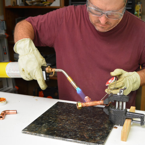
STEP 12: SOLDER THE FINAL ASSEMBLY TOGETHER
The final piece was pre-assembled but needed to be attached in two places. Since I'd be hitting the assembly with some incredibly hot flame, I cleared all the sawdust away and wrapped the area with a flame proof pad and a damp rag. I didn't mess around heating it too much, just enough to get the job done and the solder flowing. Can you imagine me setting the trunk on fire at this point? Nope, nope, nope!

STEP 13: THE STEAM STACK
Obviously, a "steam powered" lamp needs an exhaust pipe right? For visual interest, I'd installed threaded connectors to connect one to the piece. A pair of slip jaw pliers torqued them together.
Of course, the design would have been a lot smoother and less expensive if I'd simply used standard 1/2" fittings for the whole project. I think it looks a lot better with all kinds of pieces and sizes. Both runs of tubing actually leave the chest with 3/4" fittings and transitioned down to 1/2". The Steam stack is capped with a 1/2" to 1" adapter, and it's got a lovely soot smudge on it.

STEP 14: IT NEEDS MORE HOLES!
I cut the leather straps with a utility knife and sloooowly ran a hole saw through the face of the trunk to keep from ripping the paper veneer. What I'm now calling the "face" was actually the lid of the trunk, but I'd stood the thing on end because this particular piece has some size constraints, it would need to sit on a 4" deep shelf; this orientation was 4 1/2" deep. More on the sizing later.
The new holes would receive neat electrical gauges. I chose to add them, because Steampunk design just cries out for gauges, right?

STEP 15: MASK AND PAINT
The gauges were cheap, black plastic, and not remotely regal enough to grace the face of a vintage creation of Steampunk wizardry. So, I scuffed them up with sandpaper, masked them off with tape, and spray-painted them with a metallic bronze paint. I painted the visible kit parts and the pressure gauge that you'll see in a moment.

STEP 16: IT'S IN THE DETAILS
When the paint dried, I pre-drilled the holes to attach the gauges and screwed them in by hand. After some unsuccessful hunting around town, I'd finally found 5/8" antique brass screws. They fairly closely matched the spray paint and the torched patina of copper.

ELECTRICAL ENGINEERING
Because it's Powered by Steam
I picked up a lamp kit at the home center. It included the bulb socket and all the various widgets you need to turn nearly anything into a cool DIY lamp. Some of the kits were labeled "bottle lamp kit." I assume it's labeled that way in case you want to take the easy route and craft yourself a whimsical wine bottle lamp with glitter, Popsicle sticks, and unicorn stickers, instead of torching a bad-ass, gauge-covered, Steampunk lamp with flame-scorched copper.
STEP 17: FEEDING THE LAMP CORD
A small, but heavy, metal nut tied to the end of a piece of string, was able to tumble through the twisting path of pipe as I tipped and spun the whole assembly around like a marble maze game. Once the string was through the maze, the lamp cord could be attached and gently pulled through. If the rubbery insulation was to get skinned, there'd likely be a direct electrical short later.
Tip: Don't have a direct electrical short. You will witness some sparks and smoke escape your beloved lamp before trudging out to reset a circuit breaker.

STEP 18: INSTALL THE SWITCH
Now you can control the lamp with the little push lever thingie that goes through the light socket but, honestly, that's how a chump would do it. (I later snipped mine off with some cutting pliers - after making sure it was in the "on" position.)
I drilled another hole in the side and installed a toggle switch. I couldn't find any antique looking ones but silver seems to look just fine. I'd picked up a SPDT switch, which stands for "Single Pole, Double Throw." Single Pole means there's only one, live "hot" source of power coming in to it. Double Throw means there were two different "on" positions. This puppy would allow for two, different powered options to work, depending on the position of the switch. An On / Off switch, SPST, "Single Pole, Single Throw" would be simple. But you know, I don't usually go for simple.
The switch pokes through from the inside and gets locked in place with an included threaded nut.

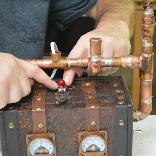
STEP 19: ADDING A NIGHT LIGHT
This project took me on a never-ending tour of our fair city's DIY establishments to forage the necessary parts. An obliging electronics store provided a 120 volt, red indicator light. It snapped in through another fresh hole in the mini-trunk.

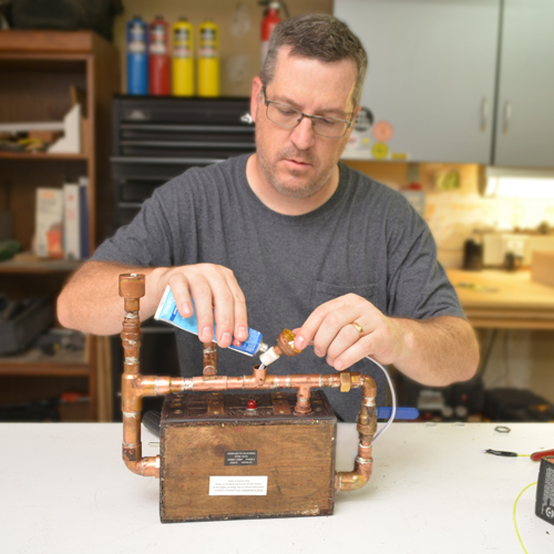
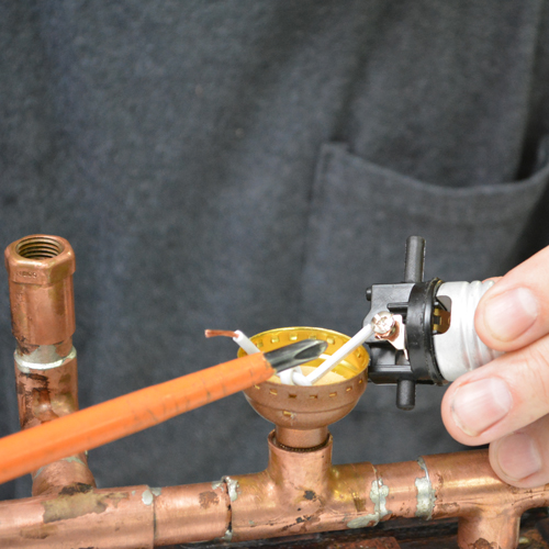
STEP 20: THE LAMP SOCKET
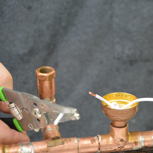
The lamp kit came with an assortment of rubbery stoppers with threaded holes down their centers, presumably for different sized wine bottle necks. I used adhesive to glue one of them into place. The lamp socket base threads into it, over the cord.
I split the two conductors of the cord and tied them in a knot to keep them from pulling backwards. Starting from the plug end of the cord, the neutral wire is the one with the wider blade for the wall receptacle. Most cords, including this one, have a series of tiny ridges along the entire length of the cord, identifying it as the neutral. It gets wrapped around the silver screw on the lamp socket. The "hot" wire gets wrapped around the brass colored screw. I stripped the outer insulation from the copper wire, twisted the strands a couple turns, wrapped them clockwise around the appropriate screw, and tightened them down.
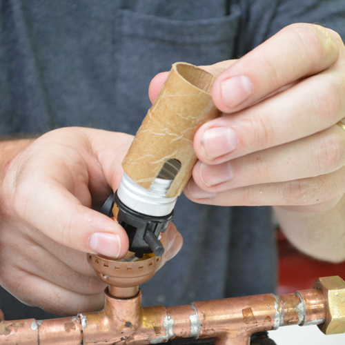
This particular kit had a cardboard insulator sleeve that slid over the inner socket before the whole assembly snapped together.
STEP 21: INTERNAL WIRING
Through a scrambled assortment of screws, nuts, washers, and wire nuts, the internal, electrical guts got assembled. In the process, I added a super long, black power cord rather than use the white one that came with the kit. A white cord would stand out to much.
Note how the screws and nuts on the switch and the gauges are open inside the box. That's a hazardous electrical situation if little hands were to access the innards while the thing is plugged in. I recommend securing the box with screws, a lock, or some other means to prevent electrical injury to an inquisitive youngster.

Yeah, it's spaghetti in there. Black wires, white wires, and a handful of wire nuts. Here's the deal, electricity is colorblind. Colors are for you to keep it all straight. Generally speaking, black is the hot, white is the grounded conductor, or the neutral, the return path of the circuit. Some of the components I was using didn't really break it up by color, so looking at my photo, ehhhhhhhh.... messy stuff.
So here's a simple diagrammatic schematic of how I wired it:

I only wired in the voltage gauge. The amp guage I received didn't work so I removed it from the circuit. It's just for looks anyway. The lamps don't pull enough amps to register more than a wiggle of the needle.
STEP 22: AND A CHERRY ON TOP
A freshly painted and scuffed up pressure gauge threaded into the 1/4" copper fitting I'd left for it. You simply must have some kind of pressure gauge for true Steampunk-ery. It's in the rules, right? This particular rascal was the same one I used on my first lamp, picked up from a local import tool store. It was about six bucks.
The lamp is a warm-glowing, vintage-style bulb, but using modern, low-energy LED technology.

I wiped the printing off the blue valve handle with some of Sweetie's nail polish remover and the project was complete.
